
Gear And Pulley Speeds
Gear Speed • Pulley Speed • Fastening Pulleys
| When
building or modifying machinery it is necessary to calculate the size
of gears or pulleys required to run a tool at a certain speed. Sometimes
it is relatively simple, if you are replacing a 3450 RPM motor with a
1725 RPM one usually all you have to do is double the size of the pulley
on the motor to run the machine at the same speed.
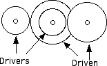
Going the other way, replacing a 1725 RPM motor with a 3450 RPM motor may not be so simple if the driving pulley on the motor is already a small diameter. The required pulley would be too small to be practical so the driven pulley would have to be replaced, however if this pulley is already fairly large, doubling the size of it would again be impractical. To get around this the pulley on the motor will have to be somewhat smaller and the pulley on the machine will have to be somewhat larger, this can be calculated using a formula. Speed of Driven Gear = Teeth on driving gear multiplied by RPM of driving gear divided by teeth on driven gear. Teeth of Driven Or Driving Gear = Teeth on gear multiplied by its RPM divided by RPM required. Speed of Last Driven Gear Divide product of driving gear sizes (number of teeth) by product of driven gear sizes and multiply quotient by RPM of first driving gear, this equals speed of last driven gear.
Ratios of Gear Drives A gear ratio indicates the speed relationship between driving and driven gears. For example if a driving gear has 15 teeth and the driven gear has 45 teeth the ratio is 45 divided by 15 which equals 3 giving a ratio of 3 to 1. Size of Driven or Driving Pulley = Diameter of pulley multiplied by its RPM divided by RPM required. Speed of Last Driven Pulley Divide product of driving pulley diameters by product of driven pulley diameters and multiply quotient br RPM of first driving pulley, this equals speed of last driven pulley.
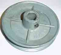
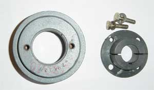
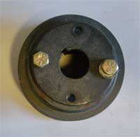
Pulleys may also be fastened to the shaft by means of a split hub.
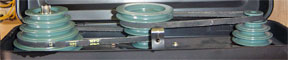
This is a two part pulley consisting of the split hub and the sheave. The outer surface of the hub and the bore of the sheave are tapered, as the two bolts are tightened the hub is forced into the sheave causing it to tighten on the shaft. To remove the pulley the bolts in the hub are loosened and bolts are tightened into the other pair of threaded holes forcing the hub out of the sheave, Variable Speeds There are applications where it is necessary to have a range of speeds for different operations, one method is to use two or more step pulleys, such as commonly used on lathes and drill presses.
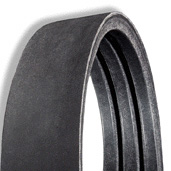
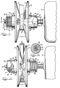
Rather than having a fixed range of speeds sometimes it is desirable to have an infinate range of speeds, this is accomplished by using movable sheaves on a pulley. As tension is put on the belt, by moving the drive farther out, the sheaves are forced apart reducing the diameter of the driving pulley.
|
||||||||||


|
|